
Advanced Steel Frame Welding Techniques for Seamless Contract Furniture
⚡ Quick Answer — What defines correctly executed steel frame welding techniques for contract furniture?
Disciplined steel frame welding techniques balance two demands that pull in opposite directions: rigid thermal control during the arc itself, achieved through fixed welding jigs that resist the distortion heat naturally introduces into raw steel, and a deliberate post-weld treatment sequence that secures structural frame durability without leaving any visual trace of the manufacturing process. Process selection — MIG for hidden structural members, TIG for visible architectural joints — and a controlled multi-stage grinding sequence applied after welding are what convert a structurally sound joint into one that also reads as unblemished under a finished coating. Skip either control and the joint will compromise either its mechanical performance or its surface quality, often without revealing which until the frame is already coated or already in service.
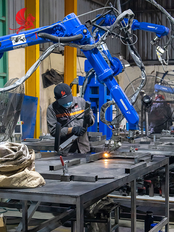
1. The Physics of the Joint: Structural vs. Aesthetic Integrity
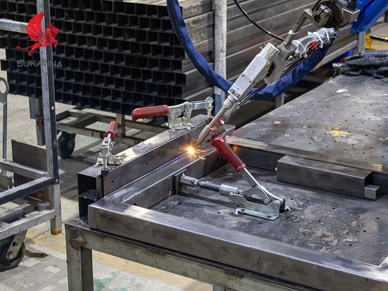
Every welded joint in a piece of contract furniture exists under two requirements that are not naturally compatible. The joint must resist intense dynamic loading — the repeated flexing of a chair frame under a guest’s weight shifting thousands of times a year, the torsional stress a table leg absorbs every time someone leans on a corner rather than the centre of the surface, the cyclic fatigue a hinge bracket experiences across a decade of daily use. At the same moment, that joint sits in full view of a paying guest in a hotel lobby or a corporate boardroom, where any visual evidence of the manufacturing process — a raised bead, an inconsistent grind line, a trace of spatter under the coating — reads as a flaw regardless of how structurally sound the connection actually is. Reconciling these two demands is the central engineering problem in commercial furniture manufacturing, and it is solved almost entirely through process discipline rather than raw material selection.
Poor weld execution compromises both requirements simultaneously, and frequently in ways that are not visible at the point of manufacture. An undercut — the narrow groove that forms at the toe of a weld bead when arc parameters run too hot or travel speed runs too fast — reduces the effective cross-section of the base metal at exactly the point where stress concentrates under load. Spatter, the small droplets of molten metal ejected during an unstable arc, creates surface irregularities that telegraph through even a properly applied powder coat. Micro-cracks, often invisible to the naked eye and only detectable under magnification or dye penetrant inspection, propagate under cyclic loading until a joint that passed initial visual inspection fails in the field eighteen months into service. Each of these defects degrades structural frame durability independently of whether the joint looks acceptable on the day it leaves the factory — which is precisely why visual inspection alone is an insufficient quality gate for any frame destined for sustained commercial use.
2. Process Selection: MIG vs. TIG in Commercial Manufacturing
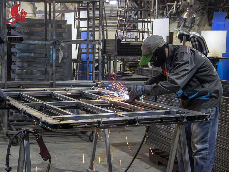
Before any arc is struck, the steel geometry itself must be locked into position. A typical MIG weld pool reaches temperatures in the range of 1,400°C to 1,600°C, and the localised expansion this generates in the surrounding base metal is substantial — a steel tube heated unevenly along one face will bow toward the heat source as it cools, and a frame welded freehand on an open bench accumulates this distortion at every joint, compounding into a chassis measurably out of square by the time the final weld is complete. On a single prototype this might be correctable by hand; across a production run of three hundred identical chairs, it is not. This is why heavy-duty welding jigs are a non-negotiable requirement in professional steel frame welding techniques — the jig locks every tube and bracket into its specified position relative to the technical drawing before the first tack weld is placed, fixing the absolute 90-degree angles and centre-to-centre spacing the design calls for, and continues holding that geometry through the full weld sequence and into the cooling phase.
With the frame geometry secured, the next decision is process selection. MIG and TIG are not interchangeable — each is the correct choice for a different category of joint within the same frame, and a single piece of furniture will often use both.
| Process | Best Used For | Heat Input Control | Spatter Risk | Post-Weld Grinding Labor |
|---|---|---|---|---|
| MIG (Gas Metal Arc) | Hidden structural chassis members — internal cross-bracing, leg-to-seat-frame connections beneath upholstery or behind panels — where appearance is irrelevant and fusion depth is the priority. | Moderate. Continuous wire feed delivers high deposition rate and deep penetration, but heat input is less precisely modulated than TIG across a single pass. | Higher. The molten wire transfer mechanism inherently ejects droplets during arc instability, requiring spatter removal as a standard finishing step. | Heavier. The thicker, less consistent bead profile requires a more substantial coarse-levelling pass before blending can begin. |
| TIG (Gas Tungsten Arc) | Visible architectural joints — exposed table leg junctions, frame elements in direct sightline — where the weld itself must read as a deliberate, refined detail. | Precise. A non-consumable tungsten electrode and independently fed filler rod give the operator direct, real-time command over heat input. | Essentially zero under correct technique — no consumable wire transfer mechanism to eject droplets. | Minimal. The tight, consistent ripple bead requires only light blending to achieve a finish-ready surface. |
A jig does not make a welder more skilled. It removes the variables that even a skilled welder cannot control by hand — and that distinction is what allows the thousandth unit in a production run to match the first.
>> Read more Wood vs. Metal Bed Frames: A Hospitality Procurement Guide
3. The Metallurgical Science of Multi-Stage Grinding
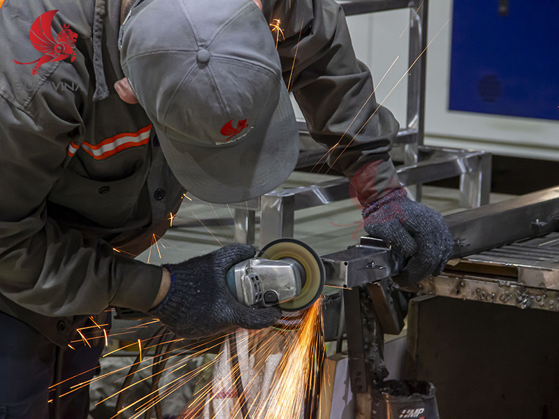
The most common and most consequential mistake at the finishing stage is treating the grinder as a tool for making a weld disappear rather than a tool for refining its surface. A weld joint carries its structural strength in two distinct zones: the weld throat, the cross-sectional dimension measured through the fusion zone that actually transmits load between the two joined members, and the weld crown, the raised bead of excess deposited metal sitting above the surrounding base metal surface. Only the crown is cosmetic. The throat is structural, and shaving into it — even by a fraction of a millimetre across an entire joint length — reduces the load-bearing cross-section at precisely the location engineered to carry the highest stress concentration in the entire assembly. An inexperienced operator chasing a perfectly flat surface under time pressure will frequently grind past the crown and into the heat-affected zone on either side, a band of material already metallurgically altered by the welding heat cycle and, for that reason, more vulnerable to fatigue cracking than the rest of the tube.
The correct technique grinds only the crown down to the surrounding surface level, leaving the fusion core and the full design throat dimension undisturbed. This requires three distinct abrasive stages applied in sequence, each with a different objective and a different consequence if skipped — the discipline that defines genuine mechanical weld joint treatment and ultimately delivers flush weld grinding at production scale rather than as an inconsistent, operator-dependent outcome.
| Stage | Abrasive Type & Grit | Objective | Risk if Skipped |
|---|---|---|---|
| 1. Coarse Levelling | Zirconia or ceramic grinding disc, 36–60 grit | Remove the bulk of the weld crown quickly, bringing the bead close to the surrounding metal surface. Volume removal only — deliberately stops short of final surface finish. | Excess crown remains, forcing later stages to over-compensate and increasing the risk of straying into the structural base metal. |
| 2. Blending | Flap disc, 80–120 grit | Smooth the transition zone between the weld and the heat-affected zone on either side, conforming to the tube’s curved profile without leaving flat facets. | A hard visual line remains exactly where the weld began and ended — the single most common cause of a visible “ghost weld” once coated. |
| 3. Micro-Finishing | Non-woven abrasive wheel, fine grade | Eliminate the fine scratch pattern left by the flap disc, producing uniform surface texture across weld zone and parent metal alike. | Surface reflectivity differs subtly between weld zone and base metal — reliably detected once coated and inspected under raking light. |
*Each stage exists because the abrasive pattern left by the previous one is too coarse for the next process to fully erase — coating does not hide surface texture, it reveals it.
4. Pre-Coating Verification: How to Audit a Seamless Joint
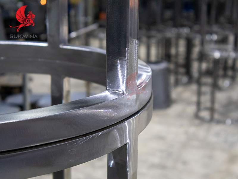
A weld joint should be fully audited before it ever enters the powder coating booth, because every defect that survives this checkpoint will be amplified — never concealed — by the coating process. Three checks form the baseline of this inspection, and each targets a distinct failure mode that becomes far more expensive to correct once a coated frame is already in finished inventory.
The first is tactile continuity. Running a bare hand or fingertip across the full length of a finished weld zone should register no detectable ridge, step, or transition at any point — if a fingertip can feel where the weld begins and ends, a powder-coated finish will show it visually under raking light, regardless of how the surface appears under direct overhead lighting in the workshop. The second is porosity inspection. Micro-pinholes — tiny voids in the weld metal caused by trapped gas during solidification — are frequently invisible to the naked eye on a freshly ground surface, but they become a serious defect during the powder coating cure cycle: as the frame heats to approximately 180°C in the curing oven, trapped air inside these pinholes expands and forces its way through the still-liquid powder film, leaving a small but highly visible bubble or crater in the finished coating. Inspecting under strong directional light, sometimes assisted by a contrasting dye penetrant on critical joints, catches this before the coating stage rather than after a finished batch has to be stripped and reworked. The third is global planarity — confirming that the overall frame geometry, not just the individual weld, sits true to the design tolerance across its full span, since a joint can be locally flush and aesthetically perfect while the frame it belongs to is still measurably out of square from an upstream fixturing error.
Only a frame that passes all three checks should proceed to furniture finishing. The coating process is not a corrective stage — it is a transparent layer that faithfully reproduces whatever surface condition exists underneath it, which is precisely why the grinding and inspection work described above carries as much weight in the final product quality as the original weld itself.
5. Engineering Insights: Technical FAQ
❓ Why do “ghost welds” appear after powder coating, and how does abrasive uniformity fix it?
A ghost weld is the faint outline of a weld joint becoming visible through an otherwise smooth powder-coated surface, typically appearing only under angled or raking light rather than direct overhead illumination. The cause is almost always a surface texture mismatch between the weld zone and the surrounding parent metal that survived the grinding stages. Powder coating does not have meaningful self-levelling capacity at the thicknesses used in furniture manufacturing — a 60–80 micron film thickness will faithfully telegraph any underlying variation in surface roughness, even when that variation is too fine to register visually on bare metal. If the coarse-levelling and blending stages leave the weld zone at a finer or coarser abrasive grit than the surrounding base metal — for example, if the original mill finish of the tube was left untouched while only the weld received grinding — the two surfaces will reflect light very slightly differently once coated, producing the ghost outline. The fix is to bring the entire visible surface, weld zone and parent metal alike, to the same final abrasive grit during the micro-finishing stage, eliminating the reflectivity differential before any coating is applied.
❓ How does tube wall thickness — for example 1.2mm versus 2.0mm or greater — affect burn-through risk?
Wall thickness directly governs how much margin for error exists at both the welding stage and the subsequent grinding stage, and the relationship is not linear — thinner material loses margin disproportionately fast. At 1.2mm wall thickness, a common specification for lighter-duty furniture components, the welding parameters must be tightly controlled to avoid burn-through, where excessive heat input melts completely through the tube wall rather than fusing the two pieces at the joint, leaving a hole instead of a weld. The acceptable grinding margin at this thickness is correspondingly thin — there is very little excess material available to remove during the crown-levelling stage before the operator risks thinning the structural wall itself, which means the welding pass needs minimal excess deposition in the first place rather than relying on grinding to correct a heavy bead. At 2.0mm or greater wall thickness, both the welding process and the grinding stage carry considerably more forgiveness: higher heat input can be applied without burn-through risk, and a more generous crown can be ground away without approaching the structural wall thickness underneath. This is why heavier-gauge tube is frequently specified not purely for the structural load rating it provides, but for the manufacturing tolerance it affords during welding and finishing.
❓ What is the structural role of internal solid steel sleeves inside a perfectly flush miter joint?
A miter joint — where two tube sections meet at an angle with their cut ends fused directly together, rather than one tube passing through or alongside the other — presents a specific structural challenge: the weld at the joint line carries the entire connection, with no overlapping material to share the load. This makes a miter joint inherently more dependent on weld quality than a lap or T-joint configuration, and it is precisely the joint geometry where designers most often want a completely seamless, gap-free aesthetic with no visible reinforcement bracket interrupting the clean lines of the frame. The engineering solution is to move the reinforcement inside the tube rather than outside it. A solid steel sleeve or internal gusset plate, sized to fit snugly within the tube’s inner diameter, is inserted across the joint line before final welding and fused to the inner wall of both tube sections. This sleeve does two things simultaneously: it adds shear and bending resistance across the joint that the weld bead alone would not provide at that wall thickness, and because it sits entirely inside the tube, it has zero impact on the external profile or the flush surface finish the design calls for. The visible joint reads as a single, continuous, seamless line from the outside, while the actual load path runs through a reinforced cross-section that the eye never sees.
 SUKAVINA CO., LTD.
• Address: Binh Chuan 44 St, An Phu Ward, Ho Chi Minh City, Vietnam
• Hotline: +84 979 034 634 / +84 931 155 155
• Email: sales@vietmetalfurniture.com
• Website: sukavinafurniture.com